Motor Monitoring Services
MCM monitors the condition of equipment driven by an electric motor, effectively using the motor itself as a sophisticated transducer. It uses advanced NASA-developed technology to provide automated set-up and fault diagnosis with minimal user intervention. It is simpler to use and more cost effective than conventional systems. MCM is applicable to a very wide range of driven equipment, including pumps, fans, compressors, and conveyors, and is particularly valuable for equipment in inaccessible or hazardous environments.
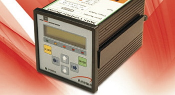
Simple to install
Installing MCM is a simple matter of connecting it to the three supply phases of the motor using simple and inexpensive transducers and mounting it in any convenient panel. It is usually located at the motor control cabinet, requiring very short cable runs and avoiding the need to install equipment in remote or hazardous areas. When first switched on, MCM carries out an automatic self-learning process during which the normal operating condition of the equipment is established. Advanced analysis techniques ensure that this training takes account of variables like speed and load, and that existing faults do not result in training errors.
Continuous monitoring of your machinery
MCM constantly takes measurements and compares them with its reference condition, in order to assess the severity and type of any developing fault. It is able to recognise abnormalities in a wide range of operating states, and is even able to extend its self-learning process when it recognises that it has moved beyond its original learning limits. This allows MCM to achieve very sensitive detection of faults without false alarms.
Reliable, automated fault diagnosis
When MCM detects a fault, it presents the results of its sophisticated analysis to the user in a simple, compelling traffic light display. This provides local staff with an immediate indication that a problem is developing. Detailed diagnostic information is provided by means of its standard networking facilities, and covers a very wide range of mechanical and electrical problems including imbalance, misalignment, bearing damage, leakage, isolation, and many others. A relay output is also provided so that specific alarm conditions can be annunciated by visual or audible warnings, or communicated to a control system.
Technical Specifications
| MCM LV Linefor low voltage motors | MCM LV – Inverterfor low voltage inverter driven motors | MCM MV & HVfor medium and high voltage motors | |
| Dimensions(W x H x L) | 96mm x 96mm x 140mm | 96mm x 96mm x 140mmFront panel mounting | 96mm x 96mm x 140mmFront panel mounting |
| Enclosure | Aluminium, RAL 7032 surface protection | Aluminium, RAL 7032 surface protection | Aluminium, RAL 7032 surface protection |
| Operations | Continuous | Continuous | Continuous |
| Ambient temperature | 0-40c (Humidity %90 RH non-condensing) | 0-40c (Humidity %90 RH non-condensing) | 0-40c (Humidity %90 RH non-condensing) |
| Class | IP20 | IP20 | IP20 |
| Applicable power range | Low voltage motors | Low voltage inverter driven motors | Medium and high voltage motors |
| Interfaces | RS 485 serial I/0, Modbus, Artebus | RS 485 serial I/0, Modbus, Artebus | RS 485 serial I/0, Modbus, Artebus |
| Digital outputs | 1 assignable relay output, user programmable NC/NO contacts |
1 assignable relay output, user programmable NC/NO contacts |
1 assignable relay output, user programmable NC/NO contacts |
| Update period | 60-120 seconds | 60-120 seconds | 60-120 seconds |
| Input Line Power Specifications | |||
| Voltage | 90-240 VAC | 90-240 VAC | 90-240 VAC |
| Power | 15 W | 15 W | 15 W |
| Frequency | 50-60 Hz | 50-60 Hz | 50-60 Hz |
| Measurement Inputs | |||
| Nominal supply frequency.fn | 50-60 Hz | 10-120 Hz | 50-60 Hz |
| Line-line rms input voltages | 380-480 VAC | 380-480 VAC | 100 V, 110 V or 120 V |
| Nominal input current range | >5 A MCMLV line units require three external 5A, 0,5Class secondary current transformers. IEC 60044-1, ANSI 57.13 |
Inverter types require external hall effect sensors or assemblies depending on motor current range |
>5 A All medium/high voltage MCM units require three external 5A secondary current transformers of appropriate primary inputs |
| Applicable standards | EN 61000 EN 60950 EN 55011 CE | EN 61000 EN 60950 EN 55011 CE | EN 61000 EN 60950 EN 55011 CE |
| Nato stock number | 6625270131535 | 6625270131535 | 6625270131535 |
| Weight | 1200 Gr | 1150 Gr | 1250 Gr |
These units can be connected to Local Area Network (LAN) using TCP / IP-RS 422/485 converters.